#ESP32 Smart Home IoT
Explore tagged Tumblr posts
Visit Tumblr Blog
Explore Tumblr blogs with no restrictions, modern design and the best experience.
Last Seen Tumblr Blogs


Fun Fact
Kazakhstan’s Minister of Communications and Informatics has blocked the Tumblr site because it contained 60 sites of terrorism, extremism, and pornography in 2015.
Text
ESP32 Power Logger with 26V Power Range and Expandable I/O for Power Monitoring
#esp32#esp32 power logger#power logger#power monitoring#electronics#innovation#iot#iot applications#projects#smart home automation#smart home technology#energy management#energy efficiency#solar power system#solar power projects#industrial automation#micropython#circuitpython#arduino#breakout#esp32 microcontroller
0 notes
Text
youtube
#SIM800L#ESP32#arduino#IOT#smart city#DIY#DIY Arduino#internet of things#smart home#dc to dc buck converter#lm2596#Youtube
0 notes
Text
CrowPanel Advance 7“ HMI von Elecrow – großes Display, großer Funktionsumfang

Mit dem CrowPanel Advance 7“ hat Elecrow ein spannendes All-in-One-Display im Sortiment, das nicht nur durch seine Größe auffällt. Das Touch-Display bringt alles mit, was man für moderne IoT- oder UI-Projekte braucht: Ein hochauflösendes IPS-Panel, einen leistungsstarken ESP32-S3 mit KI-Funktionen und zahlreiche Schnittstellen. Ich habe mir das Panel in den letzten Tagen genauer angeschaut – hier kommt mein erster Eindruck. https://youtu.be/mYx4jaoDOHQ Hinweis: Das hier vorgestellte Produkt – das CrowPanel Advance 7“ HMI – wurde mir von Elecrow kostenfrei für ein Review zur Verfügung gestellt. Der Beitrag spiegelt ausschließlich meine persönliche Meinung wider. Es gab keinerlei Vorgaben oder Einflussnahme auf Inhalt oder Bewertung.


Technische Daten – kompakt zusammengefasst
Hier die wichtigsten Eckdaten auf einen Blick: - Displaygröße: 7 Zoll IPS, 800x480 Pixel - Touch: Kapazitiver Touchscreen - Controller: ESP32-S3, Dual-Core, 240 MHz, mit KI-Unterstützung - Speicher: 16 MB Flash + 8 MB PSRAM - Schnittstellen: USB-C, GPIOs, microSD, Audio, Kamera-Port - Betriebssysteme/Sprachen: Unterstützt Arduino, LVGL, MicroPython und Meshtastic - Stromversorgung: 5 V via USB-C Diese Kombination macht das Panel zu einer interessanten Lösung für viele Anwendungen – ob als HMI (Human Machine Interface), Info-Terminal, DIY-Steuerung oder sogar als kleines Smart-Home-Display.
Ausgepackt und begutachtet
Das Panel kam gut verpackt bei mir an. Im Lieferumfang enthalten war neben dem Display auch ein passendes USB-C-Kabel sowie eine kleine Stiftleiste für GPIO-Anschlüsse. Das Gehäuse wirkt solide, die Rückseite ist sauber verarbeitet und bietet mehrere Befestigungspunkte, z. B. für den Einbau in ein Gehäuse oder Frontpanel. Was mir besonders gefallen hat: Trotz seiner Größe ist das Gerät erstaunlich leicht und flach. Das macht es deutlich einfacher, das Panel in eigene Projekte zu integrieren – z. B. in eine Steuerbox oder ein Dashboard.
Display & Touch – ein echter Hingucker
Das 7-Zoll-IPS-Display überzeugt direkt beim ersten Einschalten: Die Farben sind kräftig, die Blickwinkelstabilität ist hervorragend und die Auflösung ist für diese Größe völlig ausreichend. Auch der Touchscreen reagiert präzise und flüssig – so, wie man es von einem kapazitiven Panel erwartet. Es fühlt sich an wie ein kleiner Tablet-Bildschirm, allerdings offen für deine eigenen Ideen und Projekte.
Viel Power unter der Haube: ESP32-S3
Das Herzstück des Panels ist ein ESP32-S3 – ein leistungsfähiger Mikrocontroller mit zwei Kernen, 240 MHz Taktfrequenz und integrierten Funktionen rund um künstliche Intelligenz (KI). In Kombination mit dem großzügigen Speicher (16 MB Flash, 8 MB PSRAM) eignet sich das Gerät nicht nur für einfache UI-Anwendungen, sondern auch für Projekte mit Machine Learning oder Bildverarbeitung – zum Beispiel in Verbindung mit einer angeschlossenen Kamera.
Schnittstellen & Möglichkeiten
Ein Blick auf die Anschlussmöglichkeiten zeigt: Das Panel will mehr sein als nur ein Display. Neben USB-C (für Daten und Strom) sind auch ein microSD-Karten-Slot, ein Audio-Ausgang, ein Kamera-Port und eine GPIO-Stiftleiste vorhanden. Damit lässt sich das CrowPanel leicht erweitern und in größere Projekte einbinden – sei es zur Datenspeicherung, als Audioplayer oder zur Anbindung an Sensoren und Aktoren. Read the full article
2 notes
·
View notes
Text

ESP32 WROVER Kit, Compatible with Arduino IDE The starter kit is based on the development board from esp32 wrover. It integrates with bluetooth and wireless.A powerful dev board for IOT module project development.ESP32-WROVER series is developed by Espressif Systems, below is key features and applications are summarized: I. ESP32 Wrover Specifications - Chip Architecture - Dual-core SoC (ESP32-D0WD or D0WD-V3) with a clock speed of 80–240 MHz (dynamic frequency scaling)13 - 520 KB integrated SRAM, expandable via external SPI RAM/Flash1 - Built-in 4–16 MB SPI Flash and 8 MB SPI PSRAM (depending on model, e.g., WROVER-B/E)37 - Wireless Connectivity - 2.4 GHz Wi-Fi (802.11 b/g/n) with up to 150 Mbps throughput36 - Dual-mode Bluetooth: Classic (BT) and Low Energy (BLE)36 - Peripherals & Interfaces - SPI, I2C, UART, SDIO, Ethernet interfaces3 - Support for capacitive touch, Hall effect sensors, PWM outputs37 II. ESP32 Wrover Kit Development Environment & Tools - Programming Frameworks - Official ESP-IDF framework (FreeRTOS + LwIP stack), C/C++-based16 - Arduino IDE compatibility via ESP32 board manager28 - Optional Python/C hybrid development using Zerynth Studio5 - Hardware Debugging Tips - Use 5V power for camera modules (3.3V may cause image instability)2 - Adjust SPI pin definitions (e.g., SCK=14, MISO=12) based on hardware layout4 III. ESP32 Devkit Typical Applications - IoT Devices - Sensor networks, smart home controllers with ultra-low-power modes (sleep current Read the full article
0 notes
Text
WIRELESS MODULE with BLE and WiFi – ESP32-C3-DevKitM-1 The ESP32-C3-DevKitM-1 from Campus Component is a low-power, cost-effective solution for IoT developers. It combines WiFi and Bluetooth LE connectivity in a compact design. Featuring robust security features and efficient processing capabilities, this board is suitable for smart home devices, health monitors, and industrial IoT systems. It supports Espressif’s ESP-IDF framework.
0 notes
Text
Building a Real-Time IoT Temperature Monitoring System with ESP32, LM35 & DataStreamX
In a world driven by smart technology, real-time data monitoring has become essential — not just in industrial systems, but even in basic IoT applications like temperature sensing.
This post shows you how to build a complete IoT data pipeline using:
📟 ESP32 microcontroller
🌡️ LM35 temperature sensor
☁️ Cloudtopiaa’s DataStreamX — a powerful real-time data streaming engine
Whether you’re a beginner in IoT development or exploring edge computing for enterprise systems, this guide blends hardware, firmware, and cloud data streaming into one cohesive solution.
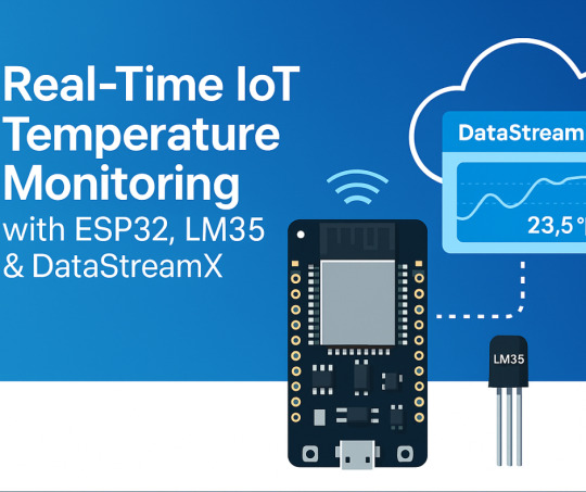
Project Overview: What We’re Building
We’ll build a real-time IoT system that:
Reads temperature using an LM35 sensor
Transmits it via MQTT protocol
Processes the data using DataStreamX (on Cloudtopiaa’s infrastructure)
Displays it on a live IoT dashboard
Use Cases: Industrial IoT Environmental monitoring Smart homes Embedded systems requiring real-time response
Components Required
ComponentDescriptionESP32 BoardWi-Fi-enabled microcontroller for IoTLM35 Temperature SensorAnalog sensor with linear outputJumper WiresFor connectionsBreadboardFor prototypingDataStreamX PlatformReal-time streaming and visualization
Hardware Setup
Connect LM35 to ESP32:
VCC → 3.3V
GND → GND
VOUT → Analog pin (e.g., GPIO34)
Power up your ESP32
Firmware: Code for ESP32
The ESP32 will:
Read analog voltage from the LM35 sensor
Convert it into Celsius
Publish the readings to DataStreamX every 5 seconds using MQTT
temperature = (analogRead(34) * 3.3 / 4095.0) * 100.0; // LM35 conversion
What is DataStreamX?
DataStreamX is a low-code, real-time data pipeline platform built into Cloudtopiaa’s cloud infrastructure. It helps developers to build resilient, scalable IoT systems easily.
Key Features:
MQTT Adapter for IoT sensors
Real-time dashboards
Event-based alerts
Edge-cloud synchronization
Secure data routing
Cloudtopiaa + DataStreamX = Instant, Scalable IoT
Setting Up DataStreamX on Cloudtopiaa
To set it up:
Log into: https://cloudtopiaa.com
Go to the DataStreamX dashboard
Create a new MQTT Adapter
Define:
Input Stream: Temperature sensor topic
Logic: (e.g., Trigger an alert if temp > 40°C)
Output Stream: Live dashboard visualization
Live Visualization: Monitor in Real-Time
Once your ESP32 starts publishing:
View real-time temperature plots
Monitor averages, minimum, and maximum values
Visualize it instantly on the Cloudtopiaa dashboard
Bonus: Trigger Smart Actions
You can create rules like:
If temperature > 50°C → Send an email alert
If temperature > 60°C → Automatically activate a cooling fan
Security & Scalability
Cloudtopiaa ensures:
🔒Encrypted communication
🔑 Role-based access control
🧾 Audit logs for compliance
📈 Scalability from 10 to 10,000+ sensors
Perfect for smart factories, research labs, and large-scale IoT deployments!
Real-World Applications
Smart Homes: Thermal alerts & automation Healthcare IoT: Patient room temperature monitoring Environmental Monitoring: Greenhouses & weather stations Industry 4.0: Machine cooling and predictive maintenance Education: STEM IoT projects with ESP32
What’s Next? Intelligent Automation
Cloudtopiaa is working to add AI feedback loops inside DataStreamX soon, enabling:
Predict overheating events
Auto-adjust environmental controls
Optimize energy consumption in real-time
Start Your IoT Journey Today
You don’t have to be a cloud architect or hardware expert to create an IoT system today. With Cloudtopiaa’s low-code dashboard, you can:
Connect your devices
Set data logic
Visualize everything in real-time!
Build with DataStreamX → Start Now
#IOT#TemperatureMonitoring#ESP32#LM35#RealTimeData#DataStreamX#Cloudtopiaa#SmartTechnology#EdgeComputing#IoTProjects#EmbeddedSystems#MQTT
0 notes
Text
Getting Started with Embedded Systems Programming

Embedded systems programming is the backbone of modern electronics. From smartwatches to washing machines, embedded systems power the intelligent functions of countless everyday devices. This guide will introduce you to the basics of embedded programming, key tools, and how to begin building your own embedded applications.
What is an Embedded System?
An embedded system is a computer integrated into a larger system or device, performing dedicated functions. Unlike general-purpose computers, embedded systems are designed for specific tasks, often with constraints on power, memory, and processing.
Examples of Embedded Systems:
Microcontrollers in home appliances
Sensor-based devices (e.g., temperature sensors, motion detectors)
Medical equipment
Automotive control systems
IoT (Internet of Things) gadgets
Core Components of an Embedded System
Microcontroller or Microprocessor: The brain of the embedded system (e.g., Arduino, STM32, ESP32).
Memory: RAM and ROM to store instructions and data.
Input/Output Interfaces: Connects to sensors, displays, motors, and communication modules.
Software: Custom firmware developed for specific functions, typically in C or C++.
Popular Programming Languages
C: Most widely used due to its efficiency and low-level hardware access.
C++: Used when object-oriented design is required.
Assembly: For highly optimized or time-critical routines.
MicroPython: Python for microcontrollers (e.g., ESP8266, Micro:bit).
Getting Started with Embedded Programming
Select Your Platform:
Beginners: Arduino (easy setup, wide community support)
Advanced: STM32, Raspberry Pi Pico, ESP32
Set Up Your Development Environment:
Install IDEs like Arduino IDE, PlatformIO, STM32CubeIDE
Download necessary drivers and board support packages
Write and Upload Code: Create simple programs like blinking an LED, then expand to sensors, displays, and communication modules.
Example: Blink an LED with Arduino
void setup() { pinMode(13, OUTPUT); // Set pin 13 as output } void loop() { digitalWrite(13, HIGH); // Turn LED on delay(1000); // Wait for 1 second digitalWrite(13, LOW); // Turn LED off delay(1000); // Wait for 1 second }
Tools and Debugging
Serial Monitor: For real-time debugging and logging.
Oscilloscope & Logic Analyzer: For electrical signal inspection.
In-Circuit Debuggers: Like JTAG or ST-Link for low-level debugging.
Best Practices
Write modular and readable code.
Use debouncing for physical inputs like buttons.
Handle memory carefully to avoid overflows.
Optimize power usage in battery-powered devices.
Conclusion
Embedded systems programming is both fun and powerful, offering endless possibilities for innovation in hardware and software. Whether you’re building a home automation project or diving into the world of IoT, understanding the basics of embedded programming gives you the foundation to create smart, responsive devices.
0 notes
Link
[ad_1] In today’s era of the Internet of Things (IoT), smart home automation has evolved from being a luxury to an accessible and essential part of modern living. This project demonstrates a scalable and real-time home automation system built around the powerful IndusBoard Coin, a compact development board based on the ESP32-S2 microcontroller. The system allows users to wirelessly control multiple AC appliances like lights and fans through an interactive web interface hosted directly on the board itself, without requiring any external cloud services or mobile apps. Unlike traditional automation systems that only offer ON/OFF control through relays, this project takes a step ahead by integrating PWM-based fan speed control, enabling smooth real-time adjustment of AC fan speed via a slider on the webpage. The board generates PWM signals from its GPIO pins, which are then sent to an AC Fan Speed Controller module that modulates the fan speed accordingly. At the same time, standard relay modules are used to control the switching of lights and fans. The Coin board’s GPIOs are connected to the relay modules, acting as electronic switches for turning appliances ON or OFF with a simple tap on the web interface.- Advertisement - The system runs on Wi-Fi Access Point (AP) mode by default, allowing users to connect their phones or laptops directly to the IndusBoard’s Wi-Fi (SSID: IndusBoard_AP) and access the control panel through a browser. However, this can easily be modified to Station Mode (STA), where the board connects to your home Wi-Fi network. In this mode, any device on the same network can access and control the system through the board’s local IP address, enabling seamless integration into existing smart homes. One of the major advantages of using the IndusBoard Coin is its high number of available GPIOs (30+ pins), which means this system is not limited to just two lights and a fan. It can be easily scaled to control additional appliances by simply connecting more relays or PWM controllers to unused GPIOs and expanding the user interface accordingly. - Advertisement - For example, additional buttons and sliders can be added to the webpage to control more lights, fans, or even future sensors like motion detectors, temperature sensors, or LDRs. Fig. 1: Home Automation System UI Bill of Material ComponentsQuantityDescriptionIndusBoard Coin1IndusBoard CoinRelay Module (5V)1Channel Relay Module (5V) 250V ACFan Speed Controller Module1Fan Speed Controller Module5V DC Adapter15V DC Circuit Diagram Fig. 2: Circuit Diagram Here, IndusBoard Coin acts as the central brain of the entire smart home automation system. It not only processes control commands but also establishes wireless communication by creating a Wi-Fi Access Point (AP mode) or by connecting to an existing Wi-Fi network using Station (STA) mode. Through this connectivity, the Coin board hosts a real-time interactive webpage that allows users to control connected appliances directly from a browser. Using its multiple GPIO pins, the board sends digital control signals to various actuators such as relays and fan speed controller modules. The relay modules, connected to GPIO pins (for example, GPIO 3 for Light 1 – GPIO 6 for Light 4), serve as the switching interface for AC appliances like bulbs or fans. These relays function as electrically operated switches, toggled by the digital HIGH or LOW outputs from the Coin board. For fans, while a regular relay can only turn the fan ON or OFF, integrating a fan speed controller module, such as an AC dimmer or a PWM-compatible controller, enables variable speed control. This module receives a PWM signal—typically from a pin like GPIO 21—where the duty cycle or firing angle of the signal determines the actual fan speed. This allows for a smooth and precise adjustment of fan speed directly through the web interface, providing a complete and advanced smart automation experience. The relay module acts like an electronic switch that isolates and safely controls the AC side of the circuit. Each relay channel on the module has input control pins connected to one of the GPIO pins of the Coin board (for instance, GPIO 3 is connected to control Light 1, and GPIO 6 to control Light 2). When a digital HIGH signal is sent from the Coin board to the relay input pin, it triggers the internal electromagnetic coil inside the relay, which closes (or opens) a switch on the AC side, allowing current to flow through the connected appliance. To connect an AC bulb or other AC appliance, the Live (L) wire from the mains power supply is first connected to the Common (COM) terminal of the relay. The Normally Open (NO) terminal is then connected to one terminal of the AC bulb or appliance. The other terminal of the appliance is connected directly to the Neutral (N) wire of the mains supply. When the relay is activated by the Coin board, the circuit between COM and NO closes, completing the path and powering ON the appliance. When the relay is deactivated, the circuit breaks, and the appliance turns OFF. This configuration ensures that high-voltage appliances are safely switched using the low-voltage logic level control from the Coin board, keeping the user and the controller board isolated from dangerous AC voltages. Multiple such relays can be connected to multiple GPIO pins on the IndusBoard Coin to control several appliances individually and in real time from the web interface. Additionally, the system can be expanded easily due to the availability of over 30+ GPIO pins on the Coin board, making it highly scalable and adaptable for larger smart home setups. Code Fig. 3: Code for Wirelessly Control Multiple AC Appliances with Web Interface The code begins with the definition of GPIO pins assigned to control various appliances like lights and fans. After that, a simple and interactive HTML webpage user interface (UI) is created within the code using embedded HTML and JavaScript, allowing users to control appliances in real time through any browser. The pinMode() function is used in the setup section to configure each GPIO pin as an output. The Wi-Fi settings are configured to enable Access Point (AP) mode, so the IndusBoard Coin can create its own wireless network for users to connect directly. The code also initializes the web server, defines routes to handle button clicks and fan speed control commands, and continuously checks for incoming client requests in the loop to ensure smooth operation of the automation system. Testing fig 4. Webpage UI for automation Now, power on the device and relay. Then, open the Wi-Fi settings on your phone or laptop and search for IndusBoard_AP. Connect to it using the password set in the code. Next, open a web browser and enter 192.168.4.1 in the address bar. From there, you can control appliances such as light bulbs, fans, and AC units. Use the slider bar to adjust the speed and the text input to set automation. The system will automatically turn off all appliances after the specified time. [ad_2] Source link
0 notes
Text
Must-Have Equipment for a High-Tech STEM Lab in Agartala Schools !

A STEM Lab in Agartala is essential for schools looking to provide hands-on learning experiences in Science, Technology, Engineering, and Mathematics (STEM). The right equipment empowers students to explore robotics, AI, IoT, and coding, preparing them for future careers in technology and innovation.
1. Robotics Kits – Bringing Machines to Life
Robotics kits are a fundamental part of a STEM Lab in Agartala. These kits allow students to build, program, and operate robots, developing skills in mechanical design, coding, and automation.
Popular Robotics Kits for Schools:
LEGO Mindstorms – Easy-to-use and perfect for beginners
VEX Robotics – Great for competitive robotics challenges
Arduino-Based Kits – Best for learning electronics and programming
Raspberry Pi Robotics – Helps students explore AI and IoT applications
By using robotics, students can understand real-world automation concepts, preparing them for industries like automotive, healthcare, and smart city development.
2. 3D Printers & Prototyping Tools – Turning Ideas into Reality
A STEM Lab in Agartala should have 3D printers that enable students to design and create physical models, turning their ideas into reality.
Why 3D Printing is Important for STEM?
Enhances creativity and problem-solving
Helps students prototype engineering and design projects
Provides hands-on learning in manufacturing and material science
Top 3D Printers for STEM Labs:
Ultimaker 3D Printers – Reliable and easy to use
Creality Ender Series – Affordable and beginner-friendly
Prusa i3 MK3 – Advanced features for high-quality prints
With 3D printing in STEM Labs, students can create robot parts, engineering models, medical prosthetics, and more.
3. AI & IoT Development Kits – The Future of Smart Technology
Artificial Intelligence (AI) and the Internet of Things (IoT) are shaping the future. A STEM Lab in Agartala must introduce students to these technologies using development kits like:
Arduino & ESP32 Kits – Learn IoT applications
Raspberry Pi with AI Camera – Explore computer vision and automation
Google AIY Kits – Hands-on experience in AI-based voice and image recognition
Students can build smart home systems, automated vehicles, and machine learning models, preparing for careers in AI and IoT development.
4. Coding and Programming Tools – Essential for Future Engineers
Every STEM Lab in Agartala must have programming tools that teach coding to students of all levels. Coding is essential for developing apps, websites, games, and AI systems.
Best Coding Platforms for STEM Education:
Scratch – Ideal for beginners
Python – Best for AI and data science
C++ & Java – Industry-standard programming languages
MIT App Inventor – Great for creating mobile applications
By integrating coding and programming into the STEM Lab, students gain logical thinking and problem-solving skills that are highly valued in tech careers.
5. Virtual Reality (VR) & Augmented Reality (AR) Kits – Immersive Learning
A STEM Lab in Agartala should include VR and AR tools to provide immersive learning experiences. These technologies allow students to visualize complex concepts and explore new environments.
Benefits of VR & AR in STEM Education:
Recommended VR/AR Kits:
Oculus Quest 2 – For interactive VR experiences
Google Expeditions – Best for classroom AR applications
Merge Cube – Affordable AR tool for schools
With VR and AR in STEM education, students gain deeper insights into scientific and engineering concepts.
6. Electronics & Circuitry Kits – Building Blocks of Innovation
Electronics play a vital role in a STEM Lab in Agartala. With circuitry kits, students can learn the basics of electrical engineering, circuit design, and embedded systems.
Top Electronics Kits for Schools:
Snap Circuits – Beginner-friendly for learning circuit design
LittleBits – Modular electronics for creative projects
Arduino Starter Kits – Best for coding and electronics integration
These kits help students develop projects in automation, renewable energy, and smart technology.
7. Smart Class Technology & Interactive Whiteboards – Enhancing STEM Learning
A modern STEM Lab in Agartala should integrate smart class technology for better engagement and visualization.
Why Smart Boards Matter?
Supports interactive simulations and real-time experiments
Enhances collaboration through digital learning
Enables video lectures and AI-powered teaching tools
Best Smart Boards for STEM Labs:
Promethean Interactive Displays
Samsung Flip 2 Digital Board
BenQ Smart Boards
Smart class technology ensures STEM education is interactive and future-ready.
8. Faculty Development & STEM Training – Preparing Educators for Innovation
A STEM Lab in Agartala is only as good as its educators. Schools must invest in faculty development programs to train teachers in STEM methodologies.
STEM Consultancy Services for Schools in Agartala
At Makers’ Muse, we offer:
STEM faculty training
Curriculum design for STEM education
STEM Lab setup and consultancy
Transform Your School with a Future-Ready STEM Lab in Agartala!
Is your school ready to provide cutting-edge STEM education? A fully-equipped STEM Lab in Agartala is essential for preparing students for future careers in technology, AI, and engineering.
We provide STEM consultancy, faculty development, and state-of-the-art STEM Lab solutions to help your school stand out. Join Our Community
Don’t wait! The future of education is here—take the first step today.
0 notes
Text
Shelly 1PM Gen4 erklärt: Installation, Integration und Vergleich mit älteren Versionen

Mit dem Shelly 1PM Gen4 hat Shelly die nächste Generation seines kompakten WLAN-Schalters mit Leistungsmessung veröffentlicht. Wer meinen Blog kennt, weiß: Die Vorgängermodelle der Gen2- und Gen3-Reihe habe ich bereits ausführlich vorgestellt und ihre Stärken im Smart-Home-Alltag analysiert. https://youtu.be/uh5eLj0Re7w In diesem Beitrag konzentriere ich mich auf die wirklich neuen Funktionen der Gen4-Version, zeige dir, wie sich das Gerät in bestehende Smarthome-Umgebungen integrieren lässt und worin die konkreten Unterschiede zu den älteren Generationen liegen. Du erfährst, ob sich ein Umstieg lohnt – oder ob der Griff zum Vorgängermodell weiterhin ausreicht.
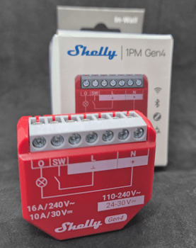
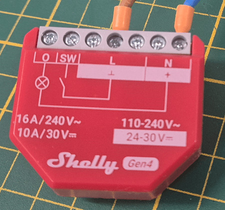
Shelly 1PM Gen4 - Vorderseite
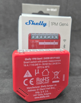
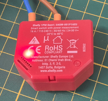
Shelly 1PM Gen4 - Rückseite
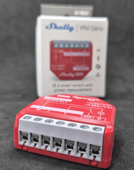
Shelly 1PM Gen4 - Klemmen
Technische Daten des Shelly 1PM Gen4
Der Shelly 1PM Gen4 ist ein kompakter WLAN-Schalter mit integrierter Leistungsmessung, der sich ideal zur Überwachung und Steuerung einzelner Verbraucher eignet. Im Vergleich zu seinen Vorgängern punktet er vor allem durch die Unterstützung moderner Smart-Home-Protokolle wie Matter und ZigBee, Bluetooth 5.0 zur schnellen Einrichtung sowie einen neuen, leistungsstarken ESP-Shelly-C68F Mikrocontroller. Hier die wichtigsten technischen Daten im Überblick: MerkmalShelly 1PM Gen4Betriebsspannung110–240 V AC / 24–30 V DCMax. Schaltleistung16 A (bei 240 V AC)LeistungsmessungJa, integriertWLAN-Standard802.11 b/g/n (2,4 GHz)BluetoothJa, für schnelle EinrichtungProzessor8 MB Flash, ESP-Shelly Chip (basierend auf ESP32)MQTT-UnterstützungJaCloud-AnbindungShelly Cloud, Shelly Smart ControlLokale APIJa (REST, MQTT, CoAP)SchutzartIP20 (nicht für Außenbereich geeignet)Abmessungen39 x 36 x 17 mmMontageUnterputz, z. B. in einer Schalterdose 💡 Hinweis: Der Shelly 1PM Gen4 ist wie gewohnt offen programmierbar und eignet sich daher ideal für die Nutzung mit Home Assistant, Node-RED, OpenHAB oder eigenen IoT-Projekten.
Einrichtung des Shelly 1PM Gen4 via Matter in Google Home
Die Einrichtung des Shelly 1PM Gen4 über Matter in Google Home ist erfreulich unkompliziert. Sobald das Gerät mit Strom versorgt wird, erkennt die Google Home App den Shelly automatisch und bietet direkt die Möglichkeit zur Kopplung. Für den Verbindungsaufbau wird zusätzlich der Matter-QR-Code benötigt, der dem Gerät auf einem kleinen beiliegenden Zettel beiliegt. Alternativ kann auch der aufgedruckte Setup-Code manuell eingegeben werden.

In den folgenden Schritten zeige ich dir anhand von Screenshots, wie du den Shelly 1PM Gen4 innerhalb weniger Minuten erfolgreich in Google Home integrierst. Wenn der Shelly 1PM Gen4 zum ersten Mal eingerichtet wird, erkennt die Google Home App das Gerät in der Regel automatisch über Matter via Bluetooth. Sollte das nicht der Fall sein – oder möchtest du den Prozess manuell starten –, dann gehst du wie folgt vor: 👉 Öffne die Google Home App und tippe unten rechts auf die Schaltfläche „+ Hinzufügen“.


Nach dem Tippen auf „+ Hinzufügen“ öffnet sich die Seite mit dem Titel „Gerät auswählen“. Hier findest du verschiedene Methoden, wie du ein neues Gerät mit Google Home verbinden kannst. 👉 Wähle die Option „Matter-kompatibles Gerät“ aus. 💡 Tipp: Die weiteren Optionen wie „Google Nest oder Partnergerät“ oder „Funktioniert mit Google Home“ sind für klassische Geräteintegration gedacht – für Shelly 1PM Gen4 mit Matter brauchst du explizit die Matter-Auswahl. Im nächsten Schritt wirst du aufgefordert, den Matter-QR-Code deines Geräts zu scannen. Diesen findest du auf einem kleinen Zettel, der dem Shelly 1PM Gen4 beiliegt. 👉 Halte den QR-Code vor die Kamera deines Smartphones, um die Einrichtung fortzusetzen.

🛑 Wichtiger Hinweis zum QR-/Setup-Code Der Matter-QR-Code, der dem Shelly 1PM Gen4 beiliegt, ist zwingend erforderlich für die Einrichtung mit Google Home. Ein entsprechender alphanumerischer Setup-Code (wie er bei vielen Matter-Geräten üblich ist) ist weder am Gerät selbst noch im Webinterface zu finden. Ich empfehle daher, den beiliegenden Zettel sofort abzufotografieren und sicher abzulegen. Zusätzlich habe ich ein Support-Ticket bei Shelly eingereicht, um zu klären, ob der Setup-Code ggf. auch digital abrufbar ist oder nachträglich erzeugt werden kann. 🔐 Tipp: Wer den Code verliert, kann das Gerät nicht erneut per Matter einrichten – eine Sicherung ist daher sehr zu empfehlen!

Nachdem du den QR-Code erfolgreich gescannt hast, startet die eigentliche Kopplung des Geräts. Dabei wird der Shelly 1PM Gen4 mit deinem Google-Konto verknüpft. 👉 Bestätige die Verbindung und folge den Anweisungen auf dem Bildschirm. Google Home baut nun eine sichere Verbindung zum Gerät auf – dieser Vorgang kann ein paar Sekunden dauern. In diesem Schritt bereitet Google Home die Einrichtung deines Shelly 1PM Gen4 vor. Dabei wird automatisch versucht, das Gerät mit dem WLAN zu verbinden, das auf deinem Smartphone oder Tablet aktiv ist. 👉 Wichtig: Der Shelly 1PM Gen4 unterstützt ausschließlich 2,4 GHz WLAN-Netzwerke – 5 GHz wird nicht erkannt.

💡 Tipp: Stelle sicher, dass dein Smartphone aktuell mit einem 2,4 GHz WLAN verbunden ist. Dual-Band-Router bündeln beide Frequenzen oft unter einem Namen – in dem Fall hilft es, das 5 GHz-Netz temporär zu deaktivieren oder ein eigenes 2,4 GHz-Netzwerk zu wählen.


Nach der WLAN-Verbindung erfolgt die automatische Einrichtung des Shelly 1PM Gen4. Dabei: - wird das Gerät final mit deinem Google-Konto verknüpft, - relevante Matter-Daten werden gespeichert, - und das Gerät wird ins Google Home-System eingebunden. 👉 Dieser Vorgang läuft vollständig automatisiert ab und dauerte in meinem Fall weniger als eine Minute. 💡 Hinweis: In dieser Phase solltest du die Google Home App nicht schließen und dein Smartphone möglichst in der Nähe des Geräts behalten. Fast geschafft! Im vorletzten Schritt der Einrichtung wirst du gefragt, in welchem Raum sich dein Shelly 1PM Gen4 befindet. Diese Angabe hilft dabei, das Gerät später in der Google Home App übersichtlich anzuzeigen und bequem per Sprachbefehl zu steuern. 👉 In meinem Fall befindet sich das Gerät im Keller, genauer gesagt in meinem Büro im Keller – deshalb habe ich hier den Raum „Keller“ ausgewählt. 💡 Tipp: Du kannst in diesem Schritt auch einen neuen Raum definieren, z. B. „Werkstatt“ oder „Technikraum“. Das ist besonders praktisch, wenn du mehrere Shellys an verschiedenen Orten nutzt.


Im letzten Schritt der Einrichtung vergibst du einen Namen für deinen Shelly 1PM Gen4. Dieser Name wird in der Google Home App angezeigt und kann auch für die Sprachsteuerung über den Google Assistant verwendet werden. 👉 Du kannst hier einen beliebigen Namen wählen, z. B. „Kaffeemaschine“, „Waschmaschine“ oder einfach „Shelly Keller“ – je nachdem, was du steuerst. 🖼️ Screenshot: Namensvergabe für das Gerät in der Google Home App 💡 Tipp: Wähle einen Namen, der sich gut per Sprache aussprechen lässt – so kannst du später mit Befehlen wie „Hey Google, schalte die Kaffeemaschine ein“ arbeiten. ✅ Nach diesem Schritt ist die Einrichtung abgeschlossen und dein Shelly 1PM Gen4 ist vollständig in Google Home integriert! Sobald dein Shelly 1PM Gen4 erfolgreich über Matter eingerichtet wurde, erscheint das Gerät als Kachel in der Google Home App. 👉 Über diese Kachel kannst du den Verbraucher ganz einfach ein- oder ausschalten. Der aktuelle Zustand wird dabei sowohl durch die Farbe der Kachel als auch durch den Status-Text deutlich dargestellt – beispielsweise „Ein“ oder „Aus“. 💡 Das sorgt nicht nur für eine intuitive Bedienung, sondern ermöglicht auch eine schnelle Statuskontrolle direkt auf einen Blick.


Shelly 1PM im Generationenvergleich: Gen2 vs. Gen3 vs. Gen4
Mit dem Shelly 1PM Gen4 bringt Shelly nicht nur Matter-Integration, sondern auch einen neuen, leistungsstärkeren Chip auf Basis des ESP32.

Shelly Geräte der Generation 2 bis 4 Die folgende Tabelle zeigt die wichtigsten Unterschiede zu Gen2 und Gen3: MerkmalShelly 1PM Gen2Shelly 1PM Gen3Shelly 1PM Gen4Versorgungsspannung110–240 V AC 24–30 V DC110–240 V AC 24–30 V DC110–240 V AC 24–30 V DCMax. Schaltstrom (AC)16 A16 A16 AMax. Schaltstrom (DC)10 A10 A10 AMax. Schaltspannung (AC/DC)240 V AC / 30 V DC240 V AC / 30 V DC240 V AC / 30 V DCLeistungsmessung✅ Ja✅ Ja✅ JaTemperatursensor intern✅ Ja✅ Ja✅ JaMQTT-Unterstützung✅ Ja✅ Ja✅ JaMatter-Unterstützung❌ Nein❌ Nein✅ JaBluetooth (BLE)✅ BLE 4.2✅ BLE 4.2✅ BLE 5.0WLAN-Protokoll802.11 b/g/n802.11 b/g/n802.11 b/g/nWi-Fi Reichweite (Innen)bis zu 30 mbis zu 30 mbis zu 30 mMCU / ProzessorESP32-U4WDHESP-Shelly-C38FESP-Shelly-C68FFlash-Speicher4 MB8 MB8 MBStromverbrauch< 1.2 W< 1.2 W< 1.2 WMaße (BxHxT)42 × 37 × 16 mm42 × 37 × 16 mm42 × 37 × 16 mmWebhooks / Scripting✅ Ja (mJs)✅ Ja✅ JaCoAP-Unterstützung❌ Nein✅ Ja✅ JaPlanung / Zeitsteuerung20 Pläne20 Pläne20 PläneKompatibilitätAlexa, Google Home, HA, ioBroker etc.wie Gen2wie Gen2 + Matter + ZigBeeMontageartUnterputz / WanddoseUnterputz / WanddoseUnterputz / WanddoseFarbe GehäuseRotRotRotFarbe KlemmeBlauSchwarzGrau 💡 Fazit: Der ESP-Shelly-C68F im Gen4 bietet mehr Rechenleistung und bessere Konnektivität (z. B. BLE 5.0), was zusammen mit der Matter-Unterstützung den Shelly 1PM Gen4 zu einer der derzeit modernsten Schaltlösungen für Smart Homes macht. Read the full article
0 notes
Text
ESP32-WROOM-32: The Tiny Powerhouse for Your Next IoT Project! 🚀🔧
Looking for a microcontroller that packs a punch? The ESP32-WROOM-32 is your best bet! 💡 This Wi-Fi + Bluetooth-enabled module is perfect for IoT, robotics, and home automation. With its dual-core processor, low power consumption, and tons of GPIO pins, it's a maker's dream. Whether you're building a smart gadget or diving into edge computing, this little beast can handle it all!
🔥 Why choose ESP32-WROOM-32? ✅ Dual-core performance ✅ Built-in Wi-Fi & Bluetooth ✅ Low power consumption ✅ Tons of connectivity options
What cool projects are you making with it? Let’s discuss! 🛠️✨ #ESP32 #IoT #DIYTech
#ESP32#Microcontroller#IoT#EmbeddedSystems#ESP32WROOM32#Electronics#DIYProjects#Arduino#WiFiModule#Bluetooth#SmartDevices#HomeAutomation#ESP32Projects#Tech#CircuitDesign
0 notes
Video
youtube
Smart Waste Management System Using ESP32 | IOT BASED GARBAGE MONITORING SYSTEM | IoT Smart Dustbin : ESP32 - SIM800L - GPS Location | IoT-Based Garbage Container System Using NodeMCU | IoT Cloud Web Server Based Garbage Monitoring System Using ESP32.***********************************************************If You Want To Purchase the Full Working Project KITMail Us: [email protected] Name Along With You-Tube Video LinkWe are Located at Telangana, Hyderabad, Boduppal. Project Changes also Made according to Student Requirementshttp://svsembedded.com/ https://www.svskits.in/ http://svsembedded.in/ http://www.svskit.com/M1: 91 9491535690 M2: 91 7842358459 We Will Send Working Model Project KIT through DTDC / DHL / Blue Dart / First Flight Courier ServiceWe Will Provide Project Soft Data through Google Drive1. Project Abstract / Synopsis 2. Project Related Datasheets of Each Component3. Project Sample Report / Documentation4. Project Kit Circuit / Schematic Diagram 5. Project Kit Working Software Code6. Project Related Software Compilers7. Project Related Sample PPT’s8. Project Kit Photos9. Project Kit Working Video linksLatest Projects with Year Wise YouTube video Links157 Projects https://svsembedded.com/ieee_2022.php135 Projects https://svsembedded.com/ieee_2021.php 151 Projects https://svsembedded.com/ieee_2020.php103 Projects https://svsembedded.com/ieee_2019.php61 Projects https://svsembedded.com/ieee_2018.php171 Projects https://svsembedded.com/ieee_2017.php170 Projects https://svsembedded.com/ieee_2016.php67 Projects https://svsembedded.com/ieee_2015.php55 Projects https://svsembedded.com/ieee_2014.php43 Projects https://svsembedded.com/ieee_2013.php1100 Projects https://www.svskit.com/2022/02/900-pr...***********************************************************1. IoT Smart Dustbin : ESP32 - SIM800L,2. efficient iot based garbage collecting smart dustbin,3. iot based garbage monitoring using Arduino,4. IoT Based Garbage Monitoring System | ESP8266 | Arduino,5. IoT based Smart Waste Management System using Arduino,6. iot based smart dustbin project report,7. iot based garbage monitoring system project report pdf,8. smart dustbin with garbage level monitoring,9. smart garbage monitoring system using blynk,10. iot based garbage monitoring system using Arduino,11. garbage monitoring system using iot,12. iot based garbage monitoring system using arduino project report,13. smart garbage monitoring system using iot ppt,14. IoT Smart Dustbin : ESP32 - SIM800L - GPS Location | Garbage Bin Waste Monitoring System,15. Iot Based Smart Garbage Bin ,16. Smart IoT-based Waste Monitoring System,17. Smart Dustbin With GPS Location,18. IOT BASED SMART GARBAGE MONITORING SYSTEM USING NODEMCU GSM GPS ULTRASONIC,19. Smart Garbage Monitoring System using Internet of Things (IOT),20. GSM Based Smart Dustbin IOT dustbin notifications | IOT garbage monitoring | dustbin level on IOT | using Arduino,21. IoT Cloud Web server Based Garbage Monitoring System,22. DIY Smart Dustbin with garbage level monitoring | IOT based Garbage monitoring system,23. Smart Garbage Monitoring System using Internet of Things (IOT) || smart bin || BIJEN,24. GSM and GPS Based Garbage and Waste Collection Bin Overflow Management System,25. How To Make An Automatic Object Sensing Smart Dustbin - DIY Project,26. How to make Smart Dustbin with Arduino | Arduino Project,27. Top 10 IoT(Internet Of Things) Projects Of All Time | 2023,28. Smart dustbin at home using arduino | Nodemcu projects | DIY,29. HOW TO MAKE GSM BASED SMART DUSTBIN USING ARDUINO,30. Smart Garbage Collecting Truck Using Arduino, GSM, GPS and Internet of Things (IOT),31. SMART DUSTBIN for SMART CITY with SMS Alerts Using Arduino – GSM,32. SMART DUSTBIN WITH LIVE GPS TRACKING AND MONITORING SYSTEM,33. Smart Trash Bin Monitoring System,
0 notes
Text
DIY Smart Home Energy Monitor with ESP32 and Home Assistant
Introduction
Managing energy consumption is a great way to reduce electricity costs and contribute to environmental sustainability. With the help of IoT, you can monitor energy usage in real-time, right from your smartphone. In this guide, we’ll build a Smart Home Energy Monitor using an ESP32 microcontroller, current and voltage sensors (like the ACS712 or SCT-013), and the MQTT protocol for data transmission. This data will be accessible on a mobile app via Home Assistant, allowing you to keep track of energy usage and optimize it effectively.
Project Overview
Objectives
Monitor power consumption in real-time for home appliances.
Display energy usage on a mobile app using MQTT and Home Assistant.
Analyze data over time to make informed decisions about energy usage.
Key Components
ESP32 (or ESP8266) microcontroller: For reading sensor data and connecting to Wi-Fi.
Current Sensor (SCT-013 or ACS712): For measuring current drawn by appliances.
Voltage Sensor: Optional, but adds more accuracy if you want to measure precise power usage.
MQTT Protocol: To send data to Home Assistant for real-time monitoring.
Home Assistant: A home automation platform to display and analyze data.
Part 1: Setting Up the Components
1. ESP32 or ESP8266 Microcontroller
Choose either the ESP32 or ESP8266 microcontroller. The ESP32 has more features and is preferred, but either will work.
Connect the ESP32 to your computer using a USB cable to program it.
2. Current Sensor (SCT-013 or ACS712)
SCT-013 is a non-invasive sensor that clamps around a wire to measure the AC current flowing through it.
ACS712 is a current sensor that can measure both AC and DC current but requires direct connection to the wire, so exercise caution with high voltage.
Wiring for SCT-013
Connect the SCT-013 sensor’s output to an analog input pin on the ESP32.
If you’re using SCT-013 with ESP8266, you’ll need an analog-to-digital converter (ADC) module since the ESP8266 has only one analog input pin with limited resolution.
Wiring for ACS712
Connect the VCC pin to the 3.3V or 5V pin on the ESP32.
Connect the OUT pin to an analog input pin on the ESP32.
Connect the GND pin to the ground (GND) on the ESP32.
3. Voltage Sensor (Optional)
A voltage sensor can be added to measure the actual voltage if you want to calculate power more accurately.
Connect the sensor’s VCC to the 3.3V on ESP32, GND to ground, and OUT to an analog input.
Part 2: Coding the ESP32 for Data Acquisition and Transmission
1. Install the Required Libraries
Make sure you have the following libraries installed in your Arduino IDE:
ESP32 or ESP8266 board support (depending on your microcontroller)
PubSubClient library for MQTT communication
WiFi library for connecting to your Wi-Fi network
2. Set Up the Code
Here’s the code to:
Read values from the current sensor.
Calculate power consumption (voltage x current if you have a voltage sensor, or assume constant voltage).
Publish data to an MQTT broker.
#include <WiFi.h> #include <PubSubClient.h>
// Wi-Fi and MQTT Broker Settings const char* ssid = "YOUR_SSID"; const char* password = "YOUR_PASSWORD"; const char* mqtt_server = "YOUR_MQTT_BROKER_IP";
// MQTT topics const char* topicPower = "home/energy_monitor/power";
WiFiClient espClient; PubSubClient client(espClient);
// Sensor parameters const int sensorPin = 34; // Analog pin for sensor (ESP32) const float voltageCalibration = 230.0; // Voltage in volts (modify as per your region) const float sensorCalibration = 0.185; // Calibration constant for ACS712 sensor
void setup() { Serial.begin(115200); setup_wifi(); client.setServer(mqtt_server, 1883); }
void setup_wifi() { delay(10); Serial.println("Connecting to WiFi..."); WiFi.begin(ssid, password); while (WiFi.status() != WL_CONNECTED) { delay(500);
Serial.print("."); } Serial.println("Connected to WiFi."); }
void reconnect() { while (!client.connected()) { Serial.print("Connecting to MQTT..."); if (client.connect("ESP32Client")) { Serial.println("Connected."); } else { delay(5000); } } }
void loop() { if (!client.connected()) { reconnect(); } client.loop();
// Read sensor data int rawValue = analogRead(sensorPin); float current = rawValue * sensorCalibration; // Adjust based on sensor
// Calculate power float power = voltageCalibration * current; // Simple power calculation (P=VI)
// Publish data to MQTT String powerStr = String(power); client.publish(topicPower, powerStr.c_str()); Serial.print("Power: "); Serial.println(power); delay(2000); // Send data every 2 seconds }
3. Upload Code
Connect your ESP32 to your computer.
Select the correct board and port in the Arduino IDE.
Upload the code to the ESP32.
Part 3: Setting Up Home Assistant and MQTT Broker
1. Set Up MQTT Broker
If you don’t have an MQTT broker, you can use Mosquitto on your local network or use an online MQTT service like HiveMQ.
Install Mosquitto on a Raspberry Pi or a computer running Home Assistant.
Configure Mosquitto by setting a username and password for secure access.
2. Configure Home Assistant
In Home Assistant, you’ll add the MQTT integration to receive data from the ESP32.
Go to Settings > Integrations and search for MQTT.
Enter your MQTT broker details and save the configuration.
3. Add a Sensor in Home Assistant
In your Home Assistant configuration file (configuration.yaml), add the following entry to display power data:sensor: - platform: mqtt name: "Home Power Consumption" state_topic: "home/energy_monitor/power" unit_of_measurement: "W" value_template: "{{ value | float }}"
Restart Home Assistant to apply changes.
You should now see a Home Power Consumption sensor in your Home Assistant dashboard.
Part 4: Testing and Using the Energy Monitor
Power on your ESP32 and ensure it’s connected to Wi-Fi.
Open Home Assistant, where you should see the real-time data of power consumption.
Monitor the data over time and optimize energy usage based on the data.
Conclusion
With this DIY Smart Home Energy Monitor, you can track power usage across various appliances in your home. This project introduces core IoT concepts such as data acquisition, MQTT communication, and integration with Home Assistant. You can further expand this setup by adding more sensors or even automating appliances based on usage patterns.
#Tech4bizsolutions #SmartHome #EnergyMonitoring #ESP32Projects #HomeAssistant #IoTProjects #DIYElectronics #MQTTProtocol #SmartHomeAutomation #PowerConsumption #EnergyEfficiency #ESP8266Projects #IoTDevelopment #HomeAutomationIdeas #TechDIY #SustainableLiving
0 notes
Text
ESP32
This week I wanted to shed some light on a seemingly unfamiliar tach amongst the general populace. If are into the tech world and have been around microcomputers like the Raspberry Pi then you’ve probably heard of this device, the ESP32. The ESP32 technically isn’t a device, it’s a chip, specifically a low-cost system on a chip (SoC). It provides Wi-Fi and sometimes both, depending on the model, to embedded devices, or IoT devices.
The ESP32 has many common uses, some of these include smart home applications like connecting light switches, thermostats, plugins, and other appliances. It is also used for remote monitoring sensors. With this, you can monitor temperature, humidity, motion, and other statistics of a room or area and send it over the cloud for real-time analysis. My grandpa has one employed just for this same reason and can adjust the temperature and fans of a room depending on the readings he receives.
Now while there are many more common daily life implementations of the ESP32 I think many people think of it for its network penetration capabilities. The ESP32 can conduct Wi-Fi sniffing which captures and analyzes Wi-Fi traffic in transit. With the correct firmware attached, the ESP32 can log unencrypted traffic and identify active devices within a limited range. ESP32 can also enact Wi-Fi jamming and when paired with its ability to act as a WAP, you now could have users logging into your Wi-Fi instead of the café’s.
This piece of hardware is going to be my next tech project and I'm excited to see what I can learn from it and do with it. I think this will open many doors in the aspect of learning new hands-on material with networks and devices as well as IoT devices.
Sources:
0 notes
Text
Introduction to Internet of Things (IoT) Programming

The Internet of Things (IoT) is revolutionizing the way we interact with devices, allowing everyday objects to connect to the internet and share data. From smart homes and wearables to industrial automation, IoT is reshaping the world. In this post, we'll dive into the basics of IoT programming and how you can start creating your own smart applications.
What is IoT?
IoT refers to a network of physical devices embedded with sensors, software, and other technologies to connect and exchange data with other devices and systems over the internet.
Key Components of IoT Systems
Devices/Sensors: Physical components that collect data (e.g., temperature sensors, motion detectors).
Connectivity: Wi-Fi, Bluetooth, Zigbee, LoRa, or cellular networks to transmit data.
Data Processing: Microcontrollers or cloud services process the incoming data.
User Interface: Web/mobile applications to monitor and control devices.
Popular IoT Hardware Platforms
Arduino: An open-source electronics platform based on simple microcontrollers.
Raspberry Pi: A small, affordable computer ideal for more powerful IoT applications.
ESP8266/ESP32: Low-cost Wi-Fi-enabled microchips widely used in IoT projects.
Languages Used in IoT Programming
C/C++: Commonly used for low-level programming on microcontrollers like Arduino.
Python: Popular for Raspberry Pi and edge computing due to its simplicity.
JavaScript (Node.js): Useful for IoT dashboards and server-side applications.
MicroPython: A lightweight version of Python optimized for microcontrollers.
Example: Blinking an LED with Arduino
void setup() { pinMode(13, OUTPUT); // Set digital pin 13 as output } void loop() { digitalWrite(13, HIGH); // Turn the LED on delay(1000); // Wait for 1 second digitalWrite(13, LOW); // Turn the LED off delay(1000); // Wait for 1 second }
IoT Data Handling and Cloud Integration
Once your devices are collecting data, you'll need to store and analyze it. Here are some common platforms:
ThingSpeak: A simple platform for IoT data logging and visualization.
Firebase: Real-time database ideal for mobile IoT applications.
AWS IoT Core: Scalable cloud service for managing IoT devices.
MQTT Protocol: Lightweight messaging protocol used for IoT device communication.
Popular IoT Projects to Try
Smart door lock controlled by a mobile app
Home temperature monitor with alerts
Motion detection security camera
Plant watering system based on soil moisture levels
Fitness tracker using accelerometers
Best Practices for IoT Programming
Use lightweight protocols and efficient code to conserve resources.
Secure your devices with strong authentication and encryption.
Plan for over-the-air (OTA) updates to patch software bugs.
Reduce power consumption for battery-powered devices.
Test in real-world conditions to ensure reliability.
Conclusion
IoT programming opens the door to endless possibilities for innovation and automation. Whether you're just blinking LEDs or building a smart home system, learning IoT programming will give you the skills to bring physical objects to life through code. Start simple, keep exploring, and gradually build smarter and more connected projects.
0 notes
Text
Introducing the S2 Mini V1.0.0 ESP32-S2 Development Board!
Looking to power up your next IoT project? Meet the S2 Mini V1.0.0 – a compact yet powerful Wi-Fi development board that's perfect for all your tech experiments.
Key Features:
4MB FLASH for plenty of storage
2MB PSRAM for speedy performance
Wi-Fi connectivity to take your projects online
Ideal for home automation, wearables, and DIY smart gadgets!
Type-C USB Interface: Easy and convenient connectivity.
27 Digital I/O Pins: Supports interrupt, PWM, I2C, single wire ADC, DAC, SPI, UART, and USB OTG.
With the ESP32-S2 at its heart, this development board is designed to handle everything from real-time data processing to seamless web communication. Whether you're a hobbyist or a professional, this is the board you need for cutting-edge projects.
Click here to purchase the product: https://dhakarobotics.com/.../1045-s2-mini-v1-0-0-esp32.../
Contact Us: +8801740298319
visit our website: https://dhakarobotics.com/

#ESP32S2#DevelopmentBoard#WiFiBoard#IoTProjects#SmartDevices#DIYTech#EmbeddedSystems#TechInnovation#HomeAutomation#WearableTech#MakersCommunity#TechGadgets#PSRAM#Microcontroller#Electronics#dhakarobotics
0 notes